| |
Other Testing Services
|
|
| |
|
|
| |
Ball Shear Testing
|
|
| |
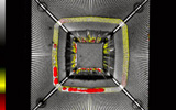
This destructive test is conducted to determine the ability of Ball Grid
Array (BGA) solder balls to withstand mechanical shear forces that may be applied
during BGA manufacturing and handling operations. In addition, Ball Shear
Testing is a valuable process' monitor to determine the reliability of
the ball attach. It can be
performed at anytime prior to second level attachment to the printed wiring
board or stress testing of the BGA module.
During the ball shear test, balls are sheared individually. The loading rate, the maximum load, and failure mode of each sheared solder ball are collected
|
|
|
|
| |
Applicable Specifications & Standards:
|
|
| |
|
|
| |
Column Pull Testing
|
|
| |
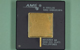
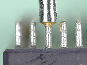
Column Pull Testing is performed to determine the strength of
the attached column interconnects and the corresponding failure mode. This method
yields quantifiable data pertaining to the quality and consistency of the solder
column, fillet, and pad. Column pull is a destructive test.
|
|
|
|
| |
|
|
| |
Lead Fatigue Testing
|
|
| |
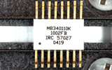
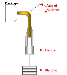
Lead Fatigue Testing is designed to check the resistance of
the leads to metal fatigue. The equipment requires attaching devices, clamps,
supports, or other suitable hardware necessary to apply a repeated bending stress
on the lead throughout the specified bend angle. The applied load, bend angle,
and number of cycles required depend upon the package type. Any device that
exhibits evidence of breakage, loosening, or relative motion between the terminal
lead and the device body when stress is removed is considered a device failure.
|
|
|
|
| |
Applicable Specifications & Standards:
|
|
| |
|
|
| |
Mark Permanency Testing |
|
| |
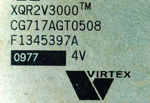
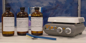
Mark Permanency Testing is needed to verify that the component
markings remain legible when subjected to repeated cleaning with common solvents.
It also verifies that the solvents will not cause deterioration of the materials
or finishes. The process is performed by subjecting the components to repeated
soaking and brushing of various commonly-used solvents in PCB assembly. In addition,
gold-lidded devices are subjected to "pre-conditioning" in heated RMA flux.
After the test, the components are inspected for marking failure or degradation
of the package. This test is applicable for all package types but
does not apply to laser-marked components.
|
|
Pass |
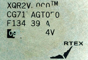
Fail |
|
|
| |
Applicable Specifications & Standards:
|
|
| |
|
|